This Battery Thermal Propagation Test System is designed for testing individual battery cells for thermal runaway and evaluating thermal propagation in rechargeable energy storage systems.
The Battery Thermal Propagation Test System enables the assessment of thermal-runaway initiation, propagation, and safety risks in batteries, providing critical data for battery design validation, safety analysis, and system-level reliability evaluation.
System Configuration
Heating System, Overcharge System, Temperature Monitoring and Data Acquisition System, Control System, Explosion-Proof Protection System, Video Monitoring System.
Test Method
1.1 Environmental Conditions
The test shall be conducted under the following environmental conditions:
- Temperature: 25 ± 5 °C
- Relative Humidity: 15% – 90% RH
- Atmospheric Pressure: 86 kPa – 106 kPa
Note: The “ambient temperature” referred to in this standard is 25 ± 2 °C.
1.2 Heating Setup
- Heating Device: Use a planar or rod-shaped heating device with its surface coated with ceramic, metal, or insulation layer.
- Heating Power: The required heating power is listed in Table A.1.
- Assembly: The heating device shall be in direct contact with the battery under test. The size of the heating device shall not exceed the heated surface area of the test object.
- Temperature Monitoring: Install temperature sensors on the side opposite the heating device (i.e., on the side away from direct heat conduction, see Figure A.1).
- Data Acquisition: Temperature data shall be sampled at intervals less than 1 second. Sensor accuracy shall be ±2 °C. The sensor tip diameter shall be less than 1 mm.
Table A.1: Selection of Heating Device Power
| Battery Energy E (Wh) | Maximum Heating Power (W) |
| E<100 | 30 – 300 |
| 100≤E<400 | 300 – 1000 |
| 400 ≤ E < 800 | 300 – 2000 |
| E ≥ 800 | > 600 |
A.1.3 Thermal Runaway Criteria
The following conditions are used to determine thermal runaway:
a) Voltage Drop of the test object occurs.
b) Monitored Temperature reaches the maximum operating temperature specified by the battery manufacturer.
c) Temperature Rise Rate (dT/dt) ≥ 1 °C/s at the monitoring point.
Thermal runaway is considered to have occurred when a) & c) or b) & c) are met.
A.1.4 Safety Termination
During heating or within 1 hour after heating, if a fire or explosion occurs, the test shall be immediately terminated.
A.1.5 Safety Requirement
The test object shall not catch fire or explode under normal test conditions.
Specifications of Battery Thermal Propagation Test System
| Product Name | Battery Thermal Propagation Test System |
| Control Method | Remote PC control with video monitoring |
| Trigger Methods | Overcharge trigger and heating trigger (standard configuration) Trigger thermal runaway of one cell within a module or battery pack to observe and evaluate thermal propagation behavior |
| DC Overcharge Trigger Control Parameters | Control Target: Overcharge of a single battery cell, or one cell within a module or battery pack Control Method: PC programmable control Controllable Parameters: Overcharge current and voltage Controller: Programmable intelligent DC power supply Overcharge Channels: 1 channel Overcharge Voltage Range: 0–10 V adjustable (customizable) Overcharge Voltage Accuracy: ≤0.3% + 2 LSB Overcharge Voltage Resolution: 0.001 V Overcharge Current Range: 0–300 A adjustable (customizable) Overcharge Current Accuracy: ≤0.3% + 2 LSB Overcharge Current Resolution: 0.1 A |
| AC Heating Trigger Control Parameters | Control Target: Built-in heating plates installed inside the battery module or battery pack (maximum power: AC 220 V, 3 kW) Control Method: PC programmable control Temperature Ramp Rate Control: 4–7 °C/min, adjustable Power Control: Multi-step or incremental power control for each heating plate (e.g. 50 W/min to 500 W/min), freely configurable Curve Generation: Real-time synchronized curve generation for intuitive visualization of test status Controller: Programmable intelligent AC variable-frequency power supply Channels: 1 channel (AC 220 V, 3 kW) |
| Output Parameters | Phase: 1Φ, 2-wire Phase Voltage: Low range 0–150 VAC / High range 0–300 VAC Frequency: 45–200 Hz, 0.1 step Maximum Current: Low range 200 V / 25 A; High range 400 V / 12.5 A |
| LED Display | Voltage (Vrms), Current (Arms), Frequency (Hz), Power (Wattage), Power Factor (PF) |
| Voltage Regulation | Power supply regulation: 0.1% Load regulation: 1% |
| Measurement Accuracy | Voltage: 0.5% FS + 5 dgt Current: 0.5% FS + 5 dgt Power: 0.5% FS + 5 dgt Frequency: 0.01% FS + 5 dgt |
| Setting Accuracy | Voltage: 1% FS Frequency: 0.1% FS |
| Current Limit Setting | Over-current protection (power output stops when current exceeds the set value) |
| Protection Functions | Over-current, Over-temperature, Short circuit, Overload |
| Communication Interface | RS-232C |
| Data Acquisition System | Voltage Channels: 4 channels Voltage Range: 0–10 V Voltage Accuracy: ≤0.2% FSR Voltage Sampling Frequency: 50 Hz Temperature Channels: 8 channels Temperature Range: 0–800 °C Temperature Accuracy: ±1 °C Temperature Sampling Frequency: 50 Hz |
| Monitoring System | Camera resolution: 1080P, 5-megapixel |
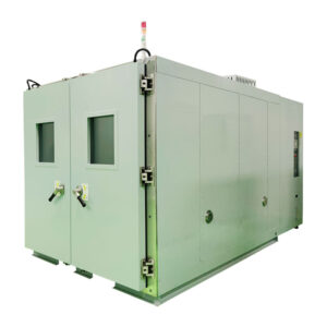
| Explosion-Proof Chamber (Optional) | Volume: 1 m³ / 1.5 m³ / 2 m³ / 4 m³ / 6 m³ / 8 m³ / 12 m³ (customizable) Steel Plate Thickness: 5 mm / 8 mm / 10 mm / 12 mm; single-layer or double-layer, customizable |
| Fire Suppression System (Optional) | Customizable fire suppression solutions: 1) Fire sprinkler system for battery packs 2) Lifting platform with water pit for immersion fire suppression 3) Integrated water tank lifting platform for immersion fire suppression |
| Equipment Dimensions | Power control cabinet: W 750 × D 750 × H 1200 mm Explosion-proof chamber and fire suppression lifting platform: customizable |
| Equipment Weight | Power control cabinet: 50 kg Explosion-proof chamber: 0.5–5 tons (optional) Water tank lifting platform: 2–5 tons (optional) |
| Power Supply | AC220V/50Hz, or AC110V/60Hz |
| Total Power Consumption | 4 kW |